How do you model novel or atypical envelope materials or assemblies?
-Loves the Leading Edge
Dear Leading Edge,
Energy modeling is a critical tool in evaluating the performance of new envelope technologies under diverse sets of conditions – building type, operation, climate conditions, and others. Laboratory testing of envelope technologies is typically limited in scale and often performed under a prescribed set of standard conditions. Field testing is usually expensive, may still be limited in scale and can really be performed only under a handful of operational and climate conditions.
The properties of traditional envelope technologies like cavity insulation and exterior rigid insulation are well understood and captured within various building energy modeling tools. However, there are emerging technologies for envelope applications, like vacuum insulation panels (VIPs), passive energy storage via phase change materials (PCMs), anisotropic materials, etc., that need additional consideration.
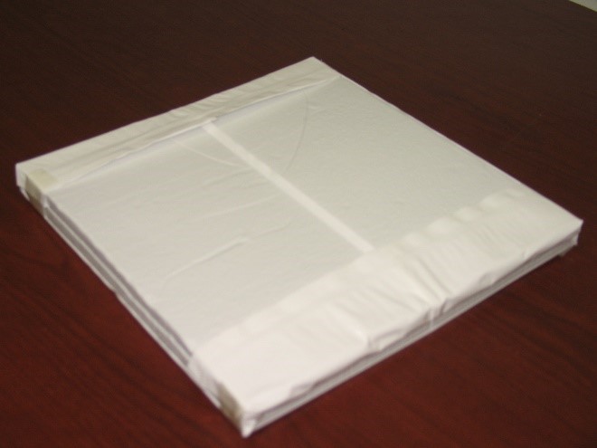
VIP with a polymer based barrier film (produced by NanoPore Inc)
For this column, I’ll focus on my experience with characterizing VIPs in envelope applications for modeling and simulations. VIPs are made of a micro- or nano-porous core material – typically fumed silica and fiberglass – that is evacuated and encapsulated within a sealed barrier film. The combination of the micro-/nano-porosity and vacuum provide VIPs an ultra-low thermal conductivity, at least 10x less than traditional fibrous or foam insulation. The rated conductivity of VIPs is what is known as the center-of-panel (COP) conductivity, i.e., the central portion of the VIP that coincides with the evacuated core and is sufficiently away from the edges. However, the performance of an envelope assembly containing VIPs needs to consider the “effective” conductivity of VIPs, which includes the heat transfer along the high-conductivity barrier film along the edges of the VIPs.
When modeling an envelope assembly containing VIPs, it is not realistic to explicitly model the heat transfer through the VIPs’ barrier films due to orders-of-magnitude difference in their length scales. The dimensions of the modeled envelope assembly can span a meter or several meters, while the thickness of the barrier film is of the order of 10-100 µm, so a ratio of ≥10e4 in largest to smallest dimension that would need to be modeled.
Instead, there are several methods of approximating the impact of the barrier films on the effective thermal conductivity of VIPs. The simplest is to refer to available literature on measurements and numerical studies focused on VIPs. For example, Sprengard and Holm (2014) performed detailed numerical analysis of the heat flows along the VIP edges for two different VIP sizes and several barrier film configurations. They noted that the effective conductivity of the VIPs can increase by 2% to 65% due to the “edge effects” depending on the VIP size and barrier film type. In general, the impact of edge effects is larger in smaller VIPs.
A more assembly-specific method is to combine small-scale measurements of VIPs and VIP assemblies with analytical methods to estimate the effective conductivity or thermal resistance of VIPs and apply them for modeling larger envelope assemblies. This is what our team did in 2017, where we measured the heat flows across multiple small-scale (0.61 m × 0.61 m) VIP assemblies in a multi-transducer heat flow meter apparatus (HFMA). This HFMA was equipped with thirteen 5.1 cm × 5.1 cm heat flux transducers which measured the heat flow through different sections of the VIP assemblies – COP areas, interfaces with two VIP edges, an interface with one VIP edge and two VIP corners, and an interface with four VIP corners. These measurements were combined with analytical calculations to estimate the effective conductivity of the VIPs. These calculations were then extrapolated to larger (2.44 m × 2.44 m) test wall assemblies containing VIPs to numerically estimate the overall thermal resistance of the test wall. The numerical estimations matched the test wall resistance measurements within 8-18%.
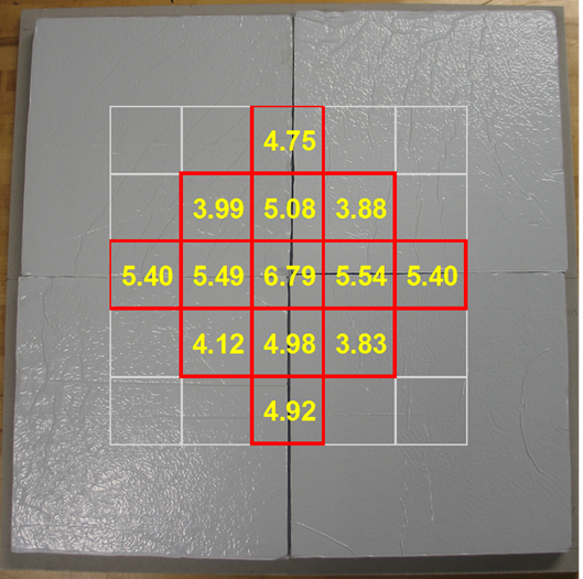
Sample heat flow measurements through different sections of a VIP assembly
In 2019, I also developed a finite element model using a “thin layer” feature in COMSOL to model the heat flows through the barrier films of VIPs within the 0.61 m × 0.61 m VIP assemblies noted above. By running parametric simulations and error minimization compared to the HFMA measurements, a set of barrier film properties (thickness and conductivity) were determined. The barrier film properties combined with the COP measurements of the VIP were used to model a 2.44 m × 2.44 m test wall assembly containing VIPs. In this case, the modeled test wall resistance was within 4.7% of the measured thermal resistance. These estimations of the effective thermal resistance of VIPs can then be used in whole-building energy modeling tools like EnergyPlus.
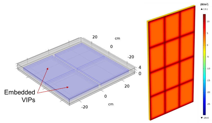
COMSOL modeling of VIPs embedded within foam boards.
As a general cautionary note, care is needed when extrapolating the results of the effective VIP conductivities to different scenarios. Some obvious things to note are the core materials and VIP dimensions. The core material has a significant impact on the initial and long term performance of VIPs. Fiberglass VIPs tend to have a lower initial thermal conductivity than silica VIPs. However, the conductivity of fiberglass VIPs rises sharply with any increase in the core pressure (from gases leaking in through compromised seals). Conversely, the rate of change of conductivity with pressure in a silica VIP is lower.
Care must also be taken not to apply the measured/modeled effective conductivity of VIPs of a given dimension to other VIPs that are of significantly different sizes or thickness. When estimating the effective conductivity of VIPs, it is recommended that VIPs of a range of dimensions and thicknesses be evaluated, and the results be applied to envelope assemblies containing VIPs of similar dimensions.
Furthermore, the conductivity of VIPs is temperature dependent. The conductivity is typically lower at lower temperatures. So instead of adopting a single, constant conductivity, a temperature-dependent conductivity function should be implemented in numerical models.
It is great to consider advanced assemblies in our building designs, and it's important to consider the steps one must take in order to accurately represent the emerging envelope technology. Luckily, there is a significant body of past and ongoing research on developing tools and models to estimate the performance of these emerging technologies to help inform the industry and begin designing buildings that utilize these technologies.

Senior Engineer, GTI Energy
The photos and graphics presented are from the author’s work performed at Oak Ridge National Laboratory, under Department of Energy funded projects.